M2MTD SYNNEX USA warehouse Physical AI POC

Prepared forTD SYNNEX logo

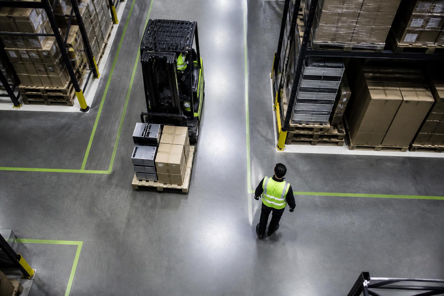
Physical AI in the Brownfield Warehouse

From perception to physical action, at the edge.

A practical path from constrained warehouse POC to repeatable Physical AI architecture.

Start with one proposed workcell and a measurable outcome.

M2M helps bring Physical AI into warehouse operations.

MEA connects edge perception with existing equipment and enterprise workflows, while preserving controller ownership.

MEA GX-100 · edge node

Reference configuration
Edge AI compute
NVIDIA Jetson AGX Orin 64GB module, up to 275 TOPS
Networking
4 GbE; PoE optional
Industrial I/O
4 DI / 4 DO; optional serial

The MEA GX-100 is the on-site node that runs perception next to the equipment and carries the physical interfaces used to connect to it. Figures above are the reference configuration, not a benchmark or a promised throughput.

01The operational problem

The warehouse is already automated. The challenge is connecting intelligence to reality.

Typical brownfield systems

Availability and relevance at the selected site are confirmed during discovery.

01

Conveyors and sorters

02

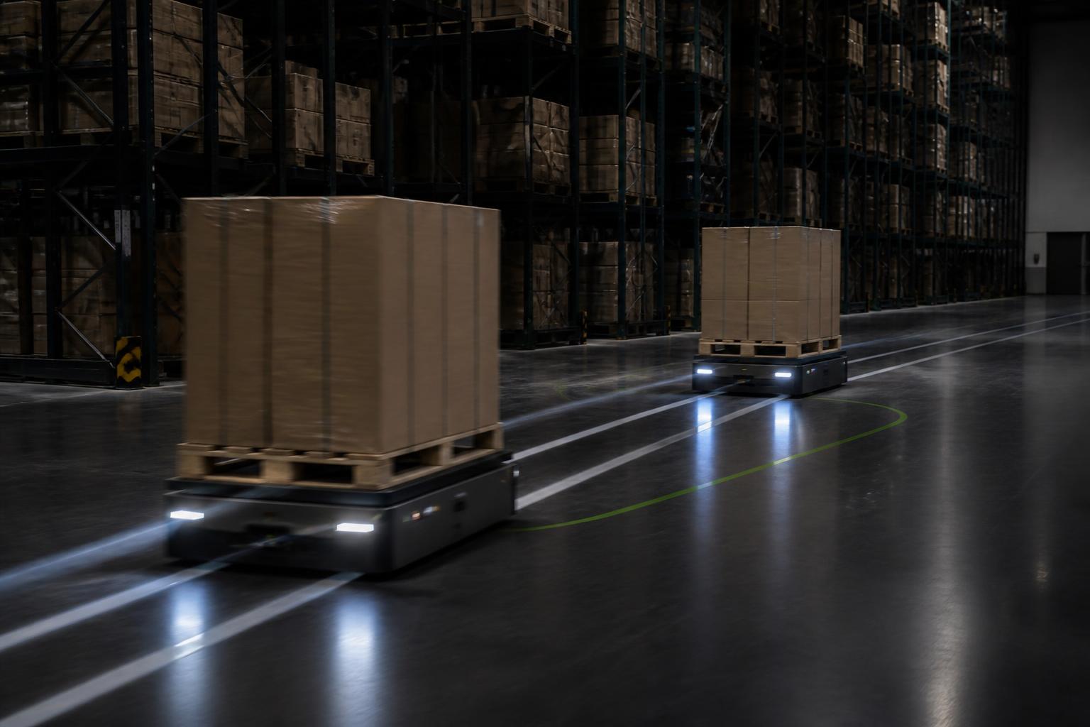
Fixed and mobile robots

03

WCS and WMS

04

ERP and enterprise workflow

05

PLCs and control cabinets

06

Photoeyes, scanners and sensors

07

Legacy OT with long service life

08

Manual exception handling

Useful perception and reliable integration have to work together: from what a camera sees to what a controller or a person is permitted to do about it.

MEA proposes an edge layer around the stack already running the building, with interfaces and operating boundaries agreed during discovery.

Proposed application and outcome

Start with randomized bin picking, pending team and TD SYNNEX selection. Measure verified pick outcomes, retries, successful picks per hour and investigation time against an agreed baseline.

Core story

  1. 01Sense
  2. 02Understand
  3. 03Decide
  4. 04Act
  5. 05Verify
  6. 06Recover
  7. 07Report

02Proposed first workcell

Randomized bin picking, pending team selection

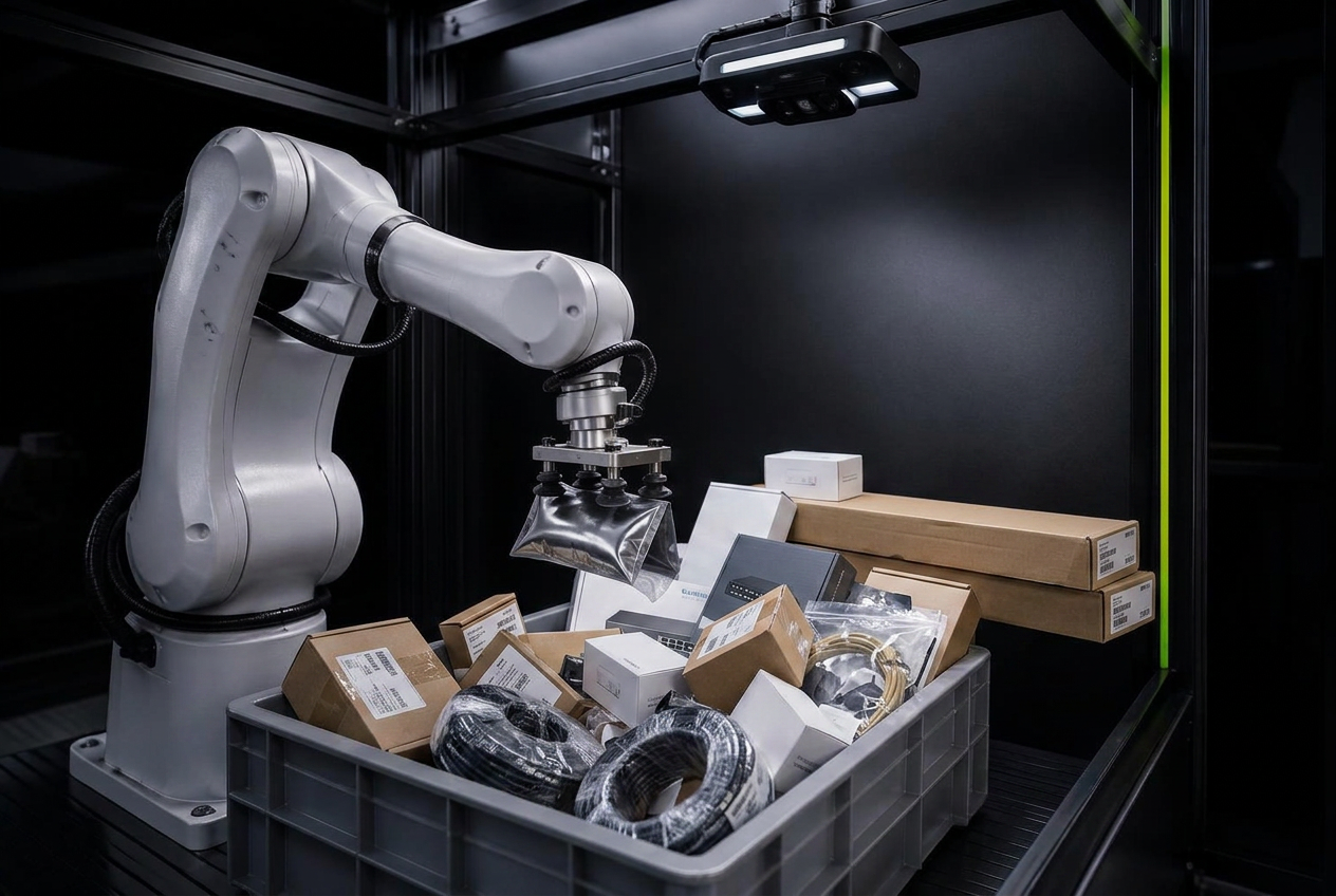
Proposed for the first evaluation, subject to team and TD SYNNEX selection: representative cartons, polybags, cylinders, irregular shapes, overlaps, reflective film and transparent packaging in a bounded workcell.

Illustrative perception output

No robot connected

All classes, depths, confidence scores and actions below are interface examples, not measured results or robot commands.

Robotic bin picking workcell with a depth camera above a tote of mixed electronics packaging
CARTON 0.94POLYBAG 0.71CHASSIS BOX 0.88ACCESSORY BAG 0.54REFLECTIVE FILM 0.41

Sensor

RGB-D, fixed mount, tote framed

Low confidence

2 objects held for re-perception

Action

Illustrative preferred grasp 0.91

Detect / segment

Proposed task: evaluate whether instance masks can separate overlapping representative products, including difficult polybags and reflective film.

Confidence handling

0.91 illustrative confidence / gate 0.65

Rigid cartonsPolybagsCylindricalIrregularOverlappingReflectiveTransparent

Scope discipline

Model choices, gripper constraints, controller interfaces and the acceptable operating envelope are confirmed and measured against representative products before any production decision.

03Verification and recovery

Production Physical AI is not just about the first attempt.

Reliability comes from verification, recovery and graceful exception handling.

  1. 01

    Attempt

    Robot executes the ranked grasp

  2. 02

    Fail

    Vacuum loss, slip or empty transfer

  3. 03

    Detect

    Verification catches the failure in cycle

  4. 04

    Re-perceive

    Scene re-captured after tote disturbance

  5. 05

    Alternate grasp

    Next ranked candidate, different approach

  6. 06

    Retry

    Bounded retry budget per item

  7. 07

    Exception

    Human handling when the budget is spent

04Models, data and validation

Select the starting approach, evaluate it, then improve only where evidence shows a gap.

Model names and versions remain selection inputs. Initial evaluation is separate from any later, approved improvement round.

Proposed stage 01

Detect the accuracy gap

Low confidence picks, repeated retries and human exceptions would be logged with the frames that produced them, so the gap is measured rather than guessed.

What it would produce

Flagged cycles per shift

Initial evaluation selects and measures the starting approach. Later improvement rounds use separately approved capture, labelling, training, validation and rollout with site agreement.

Reference approach

NVIDIA’s published FOX blueprint describes a comparable model lifecycle built on TAO, and informs the approach above. Scope is agreed per POC, and the training and validation environment is sized separately from the edge node.

View NVIDIA source(opens in a new tab)
Model stages and responsibilitiesProposed pipeline · selections and owners to confirm
Detection
Model / version
Selection pending team confirmation
Approach
Pretrained starting point; custom work only if evidence shows a gap
Inputs
RGB images
Outputs
Locations, classes, confidence
Developer
To agree: M2M, partner or OEM
Model owner
To agree
Evidence
Proposed POC validation
Segmentation
Model / version
Selection pending team confirmation
Approach
Pretrained or fine-tuned instance segmentation
Inputs
Representative tote images
Outputs
Per-item masks
Developer
To agree: M2M, partner or OEM
Model owner
To agree
Evidence
Proposed POC validation
Depth / pose
Model / version
Selection pending team confirmation
Approach
Method matched to the selected camera and items
Inputs
Depth and aligned RGB where available
Outputs
Surface geometry and candidate pose
Developer
To agree: M2M, partner or OEM
Model owner
To agree
Evidence
Proposed POC validation
Grasp ranking
Model / version
Selection pending team confirmation
Approach
Ranking against gripper and workcell constraints
Inputs
Masks, pose, gripper constraints
Outputs
Ranked candidates and confidence
Developer
To agree: M2M, partner or OEM
Model owner
To agree
Evidence
Proposed POC validation
Verification
Model / version
Selection pending team confirmation
Approach
Post-pick visual and available station-signal checks
Inputs
Post-action image and station signals
Outputs
Verified transfer, retry or exception
Developer
To agree: M2M, partner or OEM
Model owner
To agree
Evidence
Proposed POC validation
Validation and improvement planInitial evaluation separated from later rounds
Initial evaluation
Proposed evidence
Representative SKUs, materials, lighting, occlusion and difficult packaging; collection and site retention agreed first.
Data quality
Proposed evidence
Label definitions, sampling, label QA and traceability agreed before scoring.
Model work
Proposed evidence
Training or fine-tuning only where the selected starting point does not meet the acceptance envelope.
Held-out test
Proposed evidence
Unseen SKUs and difficult packaging excluded from training and used for final evaluation.
Operational measures
Proposed evidence
Failure classes, first-attempt success, retry outcomes and human exceptions compared with baseline.
Acceptance
Proposed evidence
Target, evaluation period and acceptance owner confirmed before testing.
Later rounds
Proposed evidence
New failure examples can inform a separately approved improvement round after initial evaluation.
Workload measurementTargets and measured results remain distinct
End-to-end latency
Expected target
Target to agree
Measured result
Evaluation planned
Conditions to record
Camera, resolution, model version, precision, power, thermal state and runtime
Perception throughput
Expected target
Target to agree
Measured result
Evaluation planned
Conditions to record
Frames or scenes per second; not robot picks per hour
Successful robot picks / hour
Expected target
Baseline and target to agree
Measured result
Evaluation planned
Conditions to record
Product mix, retries, motion, gripper and exception time
Memory use
Expected target
Operating envelope to agree
Measured result
Evaluation planned
Conditions to record
Models, camera concurrency, resolution, precision and retained buffers

TOPS is a compute rating, not application performance.

Capability evidence mapWhat is shown and what the POC would establish
Warehouse perception
Evidence shown
Interactive illustration
Next status
Proposed POC validation
Robotics
Evidence shown
Interactive illustration; OEM controller ownership preserved
Next status
Proposed POC validation
Training / improvement
Evidence shown
FOX-informed design reference
Next status
Later approved round
Simulation
Evidence shown
Interactive scenario illustration, not validated robot physics
Next status
Applicability assessment
Video intelligence
Evidence shown
Recorded other-environment example
Next status
Proposed warehouse evaluation
Production sensing / edge integration
Evidence shown
Prior production evidence in another environment
Next status
Reference for delivery experience

Industry references

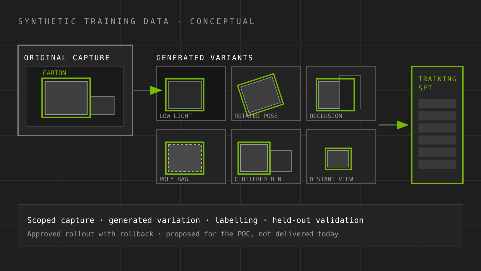
Conceptual illustration of synthetic training data: one original annotated capture expanded into six varied samples for lighting, pose, occlusion, packaging, clutter and distance, feeding a training set

Scroll the diagram sideways to read the labels

Industry reference · conceptual illustration by M2M

Generated training data

A published example of generated and annotated scene variants used to build a training set for an industrial vision model.

Comparable to the proposed step where rare packaging and lighting conditions are recreated instead of waited for.

View NVIDIA source(opens the official article in a new tab)

Data retention, labelling and any training round are agreed with the site. FOX informs the lifecycle design only; it does not establish MEA GX-100 compatibility or performance.

05Decision, action and ownership

Perception, integration and coordination have to succeed as one bounded workflow.

A warehouse running several Physical AI applications needs them reconciled at the edge, under site rules, with a clear handoff to a person when confidence runs out.

Site coordination layer

One coordinator, many specialists.

/Reads live state from perception, robots and the control layer

/Applies site rules and priority before any action is proposed

/Keeps a written record of what was decided and why

/Hands anything outside the envelope to a named human

Coordination scope for the POC is limited to the agreed workcell and observed zones.

A1

Pick agent

Randomized bin picking in the bounded workcell.

Signals
Instance masks, depth, grasp scores, cycle result
Action
Requests re-perception, alternate grasp or human exception.
A2

Material transport agent

Tote and pallet movement between staging, pick and dock.

Signals
AMR position, lane occupancy, queue depth, WCS task state
Action
Re-sequences moves and flags blocked lanes to the control layer.
A3

Verification agent

Did the physical action actually happen as instructed.

Signals
Post action frames, scan events, weight and photoeye state
Action
Confirms, disputes or escalates a completed task.
A4

Safety awareness agent

Person and forklift proximity in shared travel space.

Signals
Track history, trajectory, dwell in risk zones
Action
Raises alerts and writes evidence. No safety rated stopping.
A5

Asset health agent

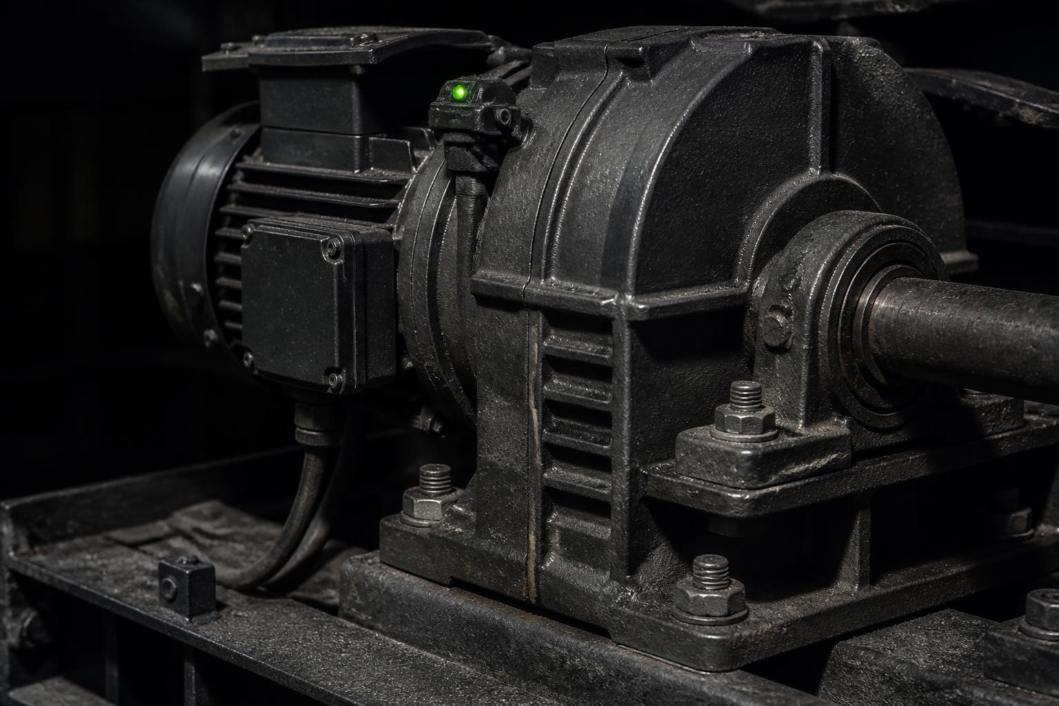
Conveyor drives, motors and gearboxes on the observed line.

Signals
Vibration, bearing temperature, current draw, run hours
Action
Flags abnormal trends for review; inspection timing requires validation.

Proposed first-workcell example

Illustrative and proposed · nothing here triggers a real action

  1. 01

    Detection

    Repeated failed cycles on the same bin, logged with the frames that produced them.

  2. 02

    Evidence

    Attempt records, grasp scores and the post-attempt frames are kept together.

  3. 03

    Investigation

    The coordinator checks whether the failures share a packaging class or a bin position.

  4. 04

    Proposed action

    Proposes re-perception with an alternate grasp, or a human exception if the class is unknown.

  5. 05

    Human approval

    The cell owner approves the retry policy change or takes the exception.

  6. 06

    Handoff

    The approved request goes to the robot controller, which keeps motion and safety ownership.

  7. 07

    Verification

    The next cycles are measured against the same failure class and added to a review backlog.

MEA role in this example

The edge node would run detection and grasp ranking in the proposed cell and record each attempt and its result.

Open for POC validation

Cycle-time budget, controller interface, and how many retries are allowed before a person is called.

Motion and safety functions stay with the existing robot and safety controllers.

Industry references

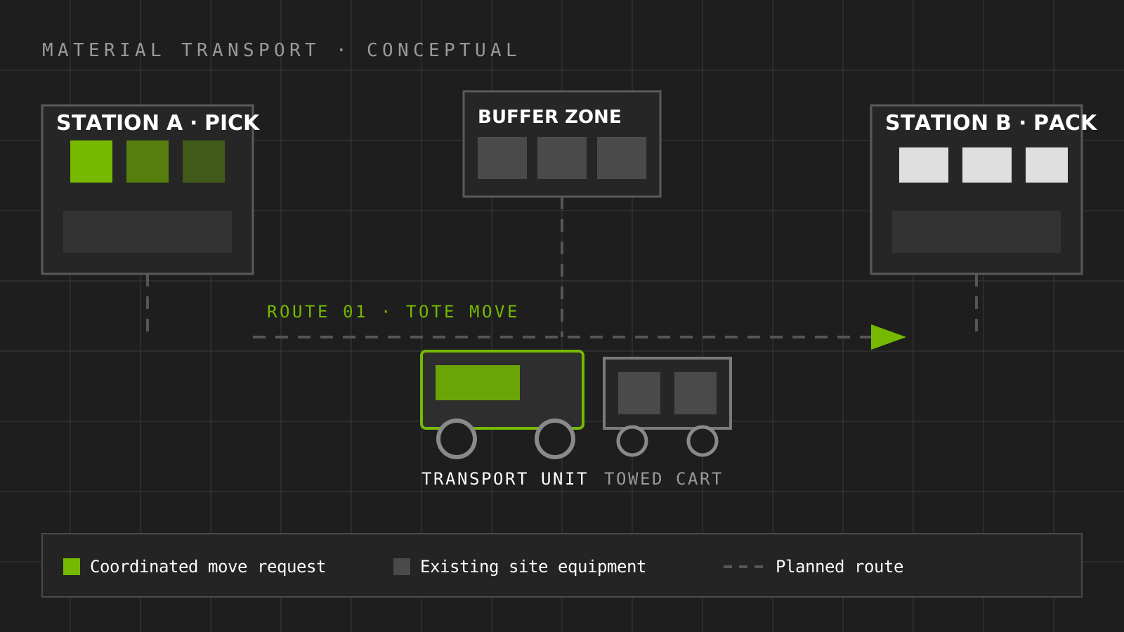
Conceptual illustration of material transport: a pick station and a pack station joined by a planned route, with a transport unit towing a cart past a buffer zone

Scroll the diagram sideways to read the labels

Industry reference · conceptual illustration by M2M

Material transport

A published example of coordinated material movement between stations on a factory floor.

Comparable to the transport agent scope proposed here, at a different site and scale.

View NVIDIA source(opens the official article in a new tab)
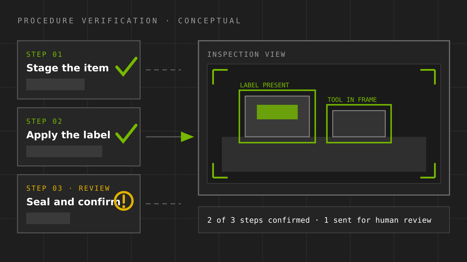
Conceptual illustration of procedure verification: three documented work steps checked against a camera inspection view with detection boxes, two confirmed and one sent for human review

Scroll the diagram sideways to read the labels

Industry reference · conceptual illustration by M2M

Procedure verification

A published example of checking that a documented work procedure was actually followed.

Comparable to the verification agent scope: confirm the physical action happened as instructed.

View NVIDIA source(opens the official article in a new tab)

06Application architecture and hardware

One integration layer, clear ownership boundaries.

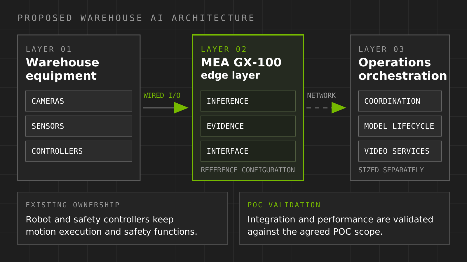
Proposed warehouse AI architecture

Architecture informed by NVIDIA’s FOX blueprint

Proposed warehouse AI architecture: warehouse cameras, sensors and controllers connect to the MEA GX-100 edge layer for inference, evidence and interfacing, which connects over the network to a separately sized operations orchestration layer, while robot and safety controllers keep motion and safety

Scroll the diagram sideways to read the labels

Layer 01 · Warehouse equipment

Cameras, sensors, controllers

Existing site equipment

  • /Fixed and depth cameras in the agreed zones
  • /Vibration, temperature and current sensing
  • /Potential existing PLC, WCS and WMS signals, subject to site confirmation

Layer 02 · MEA GX-100 edge layer

MEA GX-100

Reference configuration

  • /Inference: proposed detection, segmentation and verification workloads
  • /Evidence: local event records and retained clips
  • /Interface: wired network, digital I/O and serial paths

Layer 03 · Operations orchestration

Operations orchestration

Separately sized central compute

  • /Coordination across zones and applications
  • /Model lifecycle and scoped retraining rounds
  • /Video intelligence and operational twin

Stays with the existing owner

Robot controllers and safety controllers keep motion execution and safety functions. The edge layer requests and records; it does not perform safety-rated stopping.

Scope and POC validation

MEA GX-100 provides the edge layer. Central AI services are sized separately. Integration and performance would be validated against the agreed POC scope.

View NVIDIA source(opens in a new tab)

Core path

  1. 01

    Cameras / sensors

    RGB, depth, vibration, temperature, current, existing OT signals

  2. 02

    MEA GX-100 edge perception

    On-site detection, segmentation, depth / pose, grasp ranking and verification for the proposed picking workcell.

    Video investigation layer

    Proposed warehouse evaluation

    Video intelligence

    NVIDIA Metropolis VSS is proposed as a separately sized investigation layer that receives edge video and event references, then returns summaries and clip references for supervisor review. Controller and safety ownership remain unchanged.

    Full video intelligence detail and the recorded demonstration
  3. 03

    Policy, confidence and human approval

    Site rules, confidence gating and an operator decision point before any action is requested

  4. 04

    Existing WMS / WCS / PLC / robot controllers

    Action requests into systems that already run the floor. Motion and safety stay with the OEM controller.

  5. 05

    Verification, evidence and recovery

    Outcome checks, retained event records, retry and escalation

Proposed first workcell: randomized bin picking, pending team and TD SYNNEX selection. Edge perception can run on the MEA GX-100; the complete video intelligence stack is sized separately.

MEA GX-100 interfaces, compute and storage detail

Owned by

M2M

  • /MEA Edge
  • /Proposed edge AI runtime and integration
  • /Perception implementation, subject to agreed ownership
  • /Orchestration and evidence workflow

Owned by

TD SYNNEX

  • /WMS / WCS
  • /Warehouse process
  • /Data permissions
  • /Site access
  • /Acceptance owner to name

Owned by

Existing OT

  • /PLCs
  • /Conveyors
  • /Photoeyes
  • /Sensors
  • /Legacy equipment

Owned by

Robot OEM

  • /Robot controller
  • /Safety controller
  • /Motion execution

Interfaces are not integration

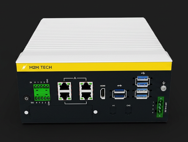
The MEA GX-100 provides the physical connection paths. Protocol and controller compatibility is confirmed during discovery, and the robot and safety controllers keep motion and safety ownership.

MEA GX-100 edge AI device with Ethernet, USB and industrial I/O connections

MEA hardware

MEA GX-100, the edge node for the POC.

The proposed edge-perception workload can be evaluated on the MEA GX-100. The complete VSS, VLM and search infrastructure must be sized separately based on camera count, models, latency, retention and workload requirements.

Enclosure, cable routing, power conditioning, site airflow and the final mounting position are selected for the work area. Cellular use may require thermal derating.

Compute module

NVIDIA Jetson AGX Orin 64GB

AI performance

Up to 275 TOPS (reference figure, not a throughput guarantee)

Memory

64GB 256-bit LPDDR5 DRAM

Networking

4 x 10/100/1000 Mbps; PoE optional (IEEE 802.3af/at)

USB

4 x USB 3.2 Gen 2 (10 Gbit/s), 2 x USB 2.0

Industrial I/O

4-ch DI, 4-ch DO; serial ports optional

Onboard storage

64GB eMMC; NVMe M.2 2280 optional, not installed at base

Power input

9 ~ 36 VDC, 16-4A

Cooling and range

Fanless; -10 ~ +60 °C with 0.7 m/s airflow (MaxN mode)

Reference platform specification for the MEA GX-100. It is not a confirmed installed bill of materials; the supplied configuration is agreed per deployment.

Reference specification

0 of 7 specification groups expanded

Processor and memoryCompute module, CPU, GPU, memory and onboard storage7
Compute module
NVIDIA Jetson AGX Orin 64GB
CPU
12-core Arm Cortex-A78AE v8.2 64-bit, 3MB L2 + 6MB L3
GPU
2048-core Ampere GPU with 64 Tensor Cores; max operating frequency 1.3 GHz
AI performance reference
Up to 275 TOPS
Memory
64GB 256-bit LPDDR5 DRAM
eMMC
64 GB
NVMe
Optional, not installed at base

NVMe storage is an option selected per deployment.

I/O, network and displayEthernet, HDMI, USB, digital I/O, optional serial7
Ethernet
4 x 10/100/1000 Mbps (optional PoE support, IEEE 802.3af/at)
Display
HDMI (max. resolution 3840 x 2160 @ 60Hz)
USB
2 x USB 2.0, 4 x USB 3.2 Gen 2
Digital I/O
4-ch DI, 4-ch DO
Power switch
1 x power ON/OFF button
Serial ports (optional)
Optional: 2 × RS-232/422/485 serial ports, exposed externally with the selected option.
OTG USB
1 x Micro USB
Expansion and securitymPCIe, SIM, M.2, TPM, wireless, GMSL6
Mini PCIe
2 x mPCIe (signal: PCIe + USB)
SIM
2 x Nano SIM slots

SIM slots do not mean a cellular modem is installed.

M.2
1 x M.2 3052 (B-Key, signal: USB)
TPM (optional)
1 x TPM 2.0
Wireless (optional)
Wi-Fi and 5G / GNSS modules are optional and selected per deployment.
GMSL (optional)
GMSL 2.0 camera input with FAKRA connectors

GMSL channel count is confirmed with the selected configuration.

StorageeMMC and optional NVMe M.2 22802
M.2
1 x M.2 2280 (M-Key, NVMe, signal: PCIe x4), optional
eMMC
64 GB
PowerInput range1
Input voltage
9 ~ 36 VDC, 16-4A

Range notation reproduced exactly as printed in the source.

Environment and mechanicalTemperature, humidity, vibration, shock, dimensions, mounting9
Operating temperature
-10 ~ +60 °C with 0.7 m/s airflow (MaxN mode)

Depends on the installation situation and interface connection. Derating of the maximum operating temperature is possible when a cellular LTE module is used.

Operating humidity
95% @ 40 °C (non-condensing)
Vibration
3 Grms @ 5 ~ 500 Hz, random, 1 hr/axis
Shock
10 G / 11 ms
Cooling
Compact fanless design
Dimensions (W x D x H)
192 x 230 x 87 mm (7.55" x 9.05" x 3.43")
Drawing dimensions
191.60 x 229.80 x 87.00 mm

Dimensional drawing figures, kept separate from the specification table figures.

Weight
4.5 kg (9.9 lb)
Installation
Desktop / wall mount; DIN-rail mounting with the optional kit

The DIN rail mounting kit is optional and is not included.

Software and certificationsBoard support package and certifications2
BSP / JetPack
Above 5.0
Certifications
UL / CB / CE / FCC / BSMI / CCC (no RED certification)

Certifications do not apply to all configurations. Applicability is confirmed for the selected configuration.

Source document last updated 21-Apr-2026. All specifications are subject to change without notice.

Evidence storage and connectivity

Onboard storage · reference
64GB eMMC reference
Local capacity · optional
Optional NVMe M.2 2280; capacity selected per deployment
Retention
Video intelligence, search and retention storage are sized separately from the edge node.
Connectivity
Wired first. Wi-Fi optional, 5G/GNSS optional modules. Dual nano SIM slots do not mean a cellular modem is installed.

Sensing layer

Existing signals first, added sensing only where it is needed.

Use the signals that already exist
Where the equipment already carries usable sensors, PLC tags or an OEM data feed, MEA taps into them first. New instrumentation is only added where a needed signal is missing.
Added sensing placed at the source
When a signal has to be added, the sensor sits as close to the mechanical source as the asset allows, so stress, heat and motion register directly rather than downstream at a panel.
Mounting chosen per asset
Mounting is engineered case by case and kept as light touch and reversible as that specific machine and its warranty terms allow.
Protected routing back to the edge
Sensor lines are consolidated and run as protected paths to the MEA enclosure, clear of moving equipment and personnel routes.

Dual track edge processing

Fast signals and slow signals, handled separately.

Track A

High frequency stream

Mechanical vibration, sampled densely enough to catch micro anomalies, pre processed on the device so no raw stream has to leave the floor.

Track B

Low frequency stream

Temperature and RPM on a slower cycle, with sampling selected and validated for the measured phenomena and available processing headroom.

The monitoring path is designed to run alongside production equipment rather than inside its control loop, so intelligence is extracted without disrupting the process. The exact integration is agreed per asset with the equipment owner.

Protocol / vendor support to be confirmed during POC discovery. No specific controller, network or system compatibility is claimed ahead of site assessment.

07Operator investigation

Investigate what happened, with the source kept visible.

Ask MEA answers from structured and text event records within a displayed source window. The VSS reviews video, returns timestamps and supporting clips, and keeps the shift supervisor responsible for disposition.

Evidence center

Loading feed

Reading the event store Latest reading (event time) unknown.

Reading the event store...

MEA assistant

Ask MEA, event-log assistant demonstration

Reading the event store

Loading feed

Ask the warehouse
what happened.

A demonstration of plain language questions answered from stored event records. Answers are generated from the event text by a hosted language model, not from video search and not from an on device model. Record references are shown with every answer; playable footage is not part of this demonstration.

08POC acceptance

Observe, recommend, then earn the right to act.

01

Observe

Read only deployment. Measure detection accuracy, latency and edge reliability under real warehouse conditions.

02

Recommend

Perception feeds a decision layer that proposes an action. Execution stays supervised and is evaluated against an agreed operator baseline.

03

Act

Closed loop physical action in a bounded workcell, verified every cycle, with defined recovery and exception paths.

Proposed acceptance envelope

Pick success

Verified first-attempt and post-retry outcomes on the held-out SKU sample.

Throughput

Successful robot picks per hour, kept distinct from perception throughput.

Recovery

Failure classes, retry results and human exceptions within the agreed budget.

Investigation

Supervisor time and evidence usefulness compared with an agreed manual baseline.

What the POC needs to start

Site / environment

Representative area, power, network and mounting positions.

Constrained use case

One workcell or flow path with a clear success definition.

Representative SKU sample

Real packaging variety, not best case items.

Cameras

Existing coverage where usable, plus placement for the target zone.

Robot if applicable

Cell, controller access and OEM engagement for the acting phase.

MEA hardware

Edge compute and supporting infrastructure supplied by M2M.

WCS / PLC interfaces

Interface points and signal definitions, confirmed during discovery.

Data access

Reference data to evaluate accuracy and business outcome.

Integration requirements

Security, network and change control expectations.

Measures, baselines, targets, evaluation period and acceptance owner are agreed before evaluation. No improvement figure is claimed in advance.

09Warehouse walkthrough

One proposed workcell, with eleven additional zones available for discovery.

Randomized bin picking is highlighted as the proposed first workcell, pending team and TD SYNNEX selection. Explore the other zones as additional applications, not committed scope.

Illustrative TD SYNNEX Brownfield Distribution Center. Conceptual facility model for POC discussion. Not an actual TD SYNNEX facility layout.

Each zone panel maps an MEA GX-100 role to the proposed application. The canonical hardware specification remains in the architecture section.

ILLUSTRATIVE TD SYNNEX BROWNFIELD DISTRIBUTION CENTER01Receiving02Inboundstaging03Pallet storage04Conveyor /sorter05Piece picking06Randomized binpicking07Automated voidfill08Quality /machine vision09Predictivemaintenance10Worker /forkliftsafety11Outboundstaging12Shipping

10One edge platform, multiple use cases

Deploy the infrastructure once. Add applications over time.

Randomized bin picking illustration

01

Randomized bin picking

first attempt pick success and cycle time.

Automated void fill illustration

02

Automated void fill

material consumed per carton and damage related rework.

Predictive maintenance illustration

03

Predictive maintenance

unplanned downtime minutes.

Worker / forklift safety illustration

04

Worker / forklift safety

near miss frequency and response time.

Quality / machine vision illustration

05

Quality / machine vision

false reject rate and inspection coverage.

MEA GX-100 edge control center in a rugged enclosure with analog modules and industrial power distribution

06

Conveyor anomaly detection

unplanned line stop minutes per shift.

11Predictive maintenance

The same MEA edge infrastructure that runs vision can also monitor machine health.

Select a drive

MTR-114

Sorter induct drive

Health score

62

Vibration

4.8 mm/s RMS

Bearing temperature

61 C

Current draw

12.4 A

Illustrative condition trend

Bearing signature drifting over the last 9 days

Illustrative inspection window

Illustrative: inspect within 14 days

Illustrative abnormal-condition progression

Inspection timing requires validation

01Baseline

Normal operation

RPM, temperature and vibration held inside the learned envelope for this drive.

02Illustrative trend

Mechanical stress

A validated vibration-monitoring method may identify a change from the established operating baseline.

Current phase for this drive

03Illustrative escalation

Thermal escalation

A correlated temperature rise can add evidence for review; response timing depends on the validated method.

04Unplanned stop

Seizure

RPM collapses as the bearing fails. This is the outcome the alerting exists to avoid.

Combined signals can support detection of abnormal conditions; warning time depends on the asset and validated monitoring method.

All values and inspection windows are illustrative, not a validated forecast or measurements from a TD SYNNEX asset. The signal pattern is informed by prior M2M edge monitoring work on rotating equipment.

12Worker / forklift safety

See the interaction before it becomes an incident.

Illustrative detections and confidence scores; no live safety system connected.

FORKLIFT 0.92PERSON 0.97MONITORING / zone A3 / no risk condition

Event response

  • Alert

    Idle

  • Evidence

    No event captured

  • Workflow

    Awaiting event

Alerting and evidence only. Safety rated machine stopping is not claimed. Safety rated control integration is future scope and integration dependent.

13Simulation / digital twin

Simulate before you automate.

Camera placement, robot location, bin randomization, conveyor speed and traffic scenarios can be explored against a scene model before anyone mounts hardware on a live flow path.

Explore → Evaluate → Decide

Twin tooling applicability is assessed per site rather than assumed.

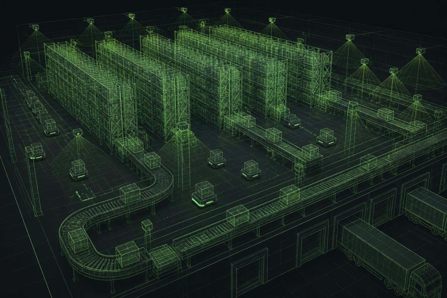
Wireframe digital twin visualization of a warehouse with camera coverage volumes
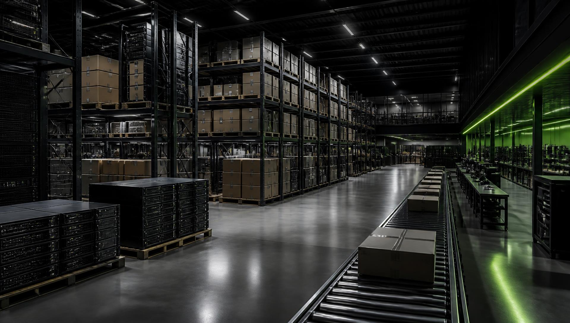
Conceptual render of a distribution center aisle with racking and conveyor
Conceptual simulated twin render of a comparable warehouse scene with sensor coverage and robot paths

Conceptual simulated twin

Conceptual physical scene

52% simulated twin / 48% conceptual physical scene. Both images are conceptual renders, not an actual customer facility.

Scene

Racking, conveyor, AMR lanes, dock faces

Synthetic variation

Pose, lighting, packaging class, occlusion

Transfer target

Same perception build, edge deployed

Conceptual renders for POC discussion.

01 RECEIVING02 INBOUND STAGING03 PALLET STORAGE04 CONVEYOR /SORTER05 PIECE PICKING06 RANDOMIZED BINPICKING07 AUTOMATED VOID FILL08 QUALITY / MACHINEVISION09 PREDICTIVEMAINTENANCE10 WORKER / FORKLIFT SAFETY11 OUTBOUNDSTAGING12 SHIPPING

Loading feed

Reading the event store

The floor plan above is driven by the event store, not by a script. In live mode the newest reading lights its zone as it lands; scrub or replay to rewind the same readings and argue over a shift after the fact.

Events

0/0

Alerts

0

Devices

0

Reading clock

--

Feed refreshed

--

Loading recorded events…

Replay of loading feed. Not measurements from a TD SYNNEX facility.

14Technology enablement

NVIDIA technologies and proposed roles

This is the M2M technology stack. NVIDIA technologies are referenced as enablers where they are technically relevant to the architecture.

Component selection is confirmed per deployment.

15Proven in the field

Production sensing and edge-integration experience.

These photographs document prior M2M production sensing and edge-integration work: edge compute, sensing modules and conditioned power deployed around existing equipment.

Rugged, independent
Rugged enclosure with power conditioned and kept separate from the line it monitors. Battery buffering is added where a site requires ride through.
Parallel monitoring architecture
In the prior deployment, monitoring ran alongside the machine controls. The integration boundary is agreed per asset and site.
Multi modal fusion
In the prior deployment, vibration, temperature and rotation were captured together and correlated at the edge.
Whole path delivered
Brackets and sensors through edge compute, local analytics and the alerting workflow operators actually use.

Relevant delivery experience. A new environment to evaluate.

The prior deployment demonstrates production sensing, mounting, power and edge-integration experience. It does not establish warehouse vision, robotics or TD SYNNEX application results.

Prior deployment in a different industry and operating environment. Results and conditions there are not a forecast of TD SYNNEX outcomes, and no figure is carried across.

Prior M2M production sensing and edge-integration evidence from another environment. Select any photo for the full view and scope.

16Scale

Validate the first workcell, then decide what can be reused.

01

One proposed workcell

A selected work area measured against the acceptance envelope agreed before evaluation.

Expansion is a decision made after the result is reviewed and accepted.

02

Multiple zones, same site

Additional zones join the same edge and coordination layer rather than starting again.

Each new zone revalidates camera and sensor configuration, interfaces, representative data and site constraints.

03

Multiple sites

Accepted interfaces and evidence can become inputs to planning for the next building.

Every site revalidates configuration, interfaces, data and local constraints. Rollout outcomes are not guaranteed in advance.

What can carry forward

An accepted result can inform a reusable reference architecture for hardware, edge software, integration and evidence. Where simulation applies, candidate layouts and workflows can be explored before physical evaluation. Any reseller or customer offer remains a separate decision after the internal result is reviewed.

M2M Tech logoforTD SYNNEX logo

Define the POC together

Select one work area, agree on the outcome, and define the first Observe phase.